Substructure Tab
This tab contains control buttons to invoke the substructure analysis/design program (Substructure) and elevation views of the bridge and selected pier.
Substructure Tab Terms
| Setting | Description |
|---|---|
| Substructure Button |
This control button is used to invoke Substructure. Upon execution, the LEAP Bridge Concrete database file is read into Substructure. If this file has been invoked in Substructure previously it will be updated with Substructure specific data and will be ready for additional data entry and modification. |
| Abutment/Pier List |
This drop-down list contains the list of all abutments/piers from the database. It is used to select an abutment or pier for closer examination or analysis and design using Substructure. |
| Design Spec | This field shows the Design Spec that was last saved or used in Substructure. |
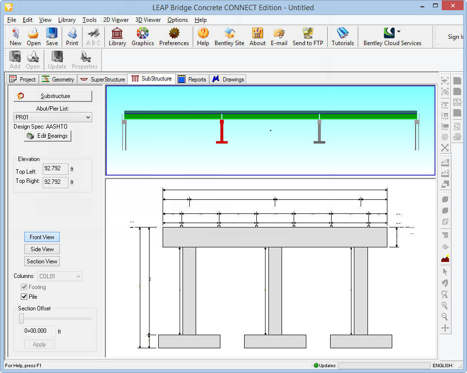
| Upper Graphical View |
This view is a 2-D elevation view of the bridge, and can also be viewed in transparent mode. The pier or abutment selected in the pier list is highlighted in this view. |
| Lower Graphical View |
This view shows two-dimensional views of the substructure components. By using the toggle buttons that appear to the left of this screen, we can see different drawings for the Font View, the Side View and the Section View. On the Section View, you can select the specific column in the pier to notice the top, middle and bottom section views. Similarly, you can turn on/off the options for showing the Footings and Piles for the selected pier section view. Right mouse clicking on this window gives additional options to zoom, print, export/save or go to the full screen viewer. |
| Bearings/Beam Seats |
Clicking this button brings up the Bearings/Beam Seats dialog box which allows editing of bearings and beam seats at the particular pier or abutment. Use the check box for Auto compute beam seat thickness to keep top of cap straight to allow the program to automatically calculate required beam seat thicknesses to account for roadway cross-section profile variation. You can also specify a minimum beam seat depth in conjunction with this option. Refer to link for visual description of input dimensions. The option 'Adjust cap ends for skew' modifies only the graphics, i.e. the 3D and 2D views, to make the edges of the support parallel to deck. |
